R2 Build: Building an Astromech from scratch!

Since the time Star Wars came out, I fell in love with the idea of astromech robots like R2D2.   While George Lucas wanted robots in his film, Ralph McQuarrie envisioned how these droids would integrate with society.

Early design sketches and concept painting of R2D2 by Ralph McQuarrie, whose artwork is driving the design aesthetic of STAR WARS REBELS including the look of Chopper the droid. © Lucasfilm Ltd. and TM. All Rights Reserved. Source: http://thestarwarssaga.com/?p=1899

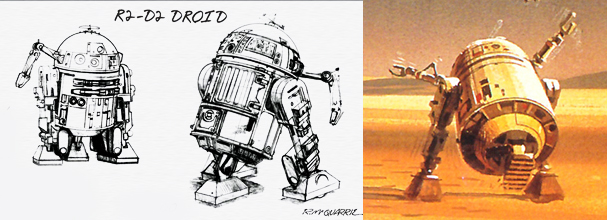
R2 does not talk and it is billed as a ‘utility droid’.   So Ralph dreamed of this compact, tool-laiden, rolling swiss-knife robot.  It’s primary language is for talking to other technology and not humans.  After being interested in robots for almost 40 years and being an engineer for almost 30, I still find this concept valid.  I think the robots of the future that will make our food, fix our stuff and clean our rooms will, in fact, evolve to be very much like R2-D2.

I was finally convinced that my time for building an astromech has come.   I saw the R2 units at the the 2015 Maker Faire in San Mateo California.   I had a great conversation with one of the booth presenters who encouraged me to check out Astromech.net, a meeting place for those who want to build their own R2 units.  Astromech.net is a community of builders as well as a repository of plans for every part in R2’s system.  In addition, a few of the community members are part of the Builder’s Council (BC) and they produce club approved small runs of parts that you can buy directly from them.   While some builders have the ability to fabricate all the parts in the R2 system by themselves, having access to high quality components is a boon to the rest of us and allows builders to get their R2 systems running sooner than later.

R2D2 and C3PO on Tatooine
C-3PO and R2-D2 at the Lars homestead on Tatooine. © Lucasfilm Ltd. & TM. All Rights Reserved. Source: http://thestarwarssaga.com/?p=2516

My next step is to get a pre-fabricated dome shell.   I researched doing this myself but it turns out that spherical aluminum shells are rather hard to find, plus cutting all the ‘pie-shapes’ out of the dome is probably left to professionals with the proper CNC equipment.  So in June, for about $500,  I ordered a dome from one of the approved BC members.

Nodebots Day – Las Vegas – July 27th 2013

SYN Shop (the Las Vegas Hacker Space)  has a cool event coming up on July 27th for javascript developers interested in learning about robotics:

You can build anything you’d like, but they’ll also be providing Sumobot Jr kits designed at SYN Shop to help you get up and running quickly. See the video for more info on the kit:

SYN Shop Podcast Episode 1 – Delta Force

This is a somewhat belated post but I eluded to the fact that there was a podcast in the works featuring @Spetku and I regarding our work on our Delta robots.

Pawel and Suz over at SYN Shop produced an excellent first podcast showing off our projects as well as a fly-through tour of SYN Shop, the Las Vegas Hackerspace!

Enjoy!

Delta Project – Part II

In part one, I talked about what a Delta is and showed my 3D printed articulating Delta arm.  Since then I’ve created a frame to hold the arm and mount motors to it.

I used Adobe Illustrator to create the artwork for the top and bottom acrylic base pieces and brought the file over to SYN Shop for cutting.

Adobe Illustrator file for laser cutting the top of the Delta frame.
Laser cut pieces and the delta frame ready for assembly.

I used threaded rods at each of the 6 hexagon corners to hold the top and bottom pieces together.

Assembled delta frame with arm hanging down.
Assembled Delta frame.

I used ViaCAD to create the mounting brackets for the servos and 3D printed them out.  I ended up doing five revisions to get it right.

The blue shows the servo mount. The yellow is the mock-up of the actual servo, which is not printed.
The blue shows the servo mount. The yellow is the mock-up of the actual servo.
Various revisions of the 3D printed servo mount.


During the process of adding the servo motors I had to re-cut the plastic top to get a better fit for the servos, but also added a few hundred holes in a grid pattern to allow mounting of the electronics as needed. I picked up three standard servos at Pololu.com.

The servos are mounted into the new brackets and there are steel wires attaching the servos to the armatures.
The motors are in the mounts and attached to the Delta frame.

Next I started adding the electronics.  I installed a Nymph board and a RobiCon connector fan-out board.

Added the Nymph, fan-out, joystick and potentiometer.
Added the Nymph and connector fan-out.

My next task was to write code.  My first goal was to just get the servos moving to make sure that the way I was driving the actuators was sane.  Here is the video below of the servos all being driven up and down in “thrust” mode.

Next time i will talk about the code that drives the Delta as well as more video showing the delta working.


Delta Project – Part I

I’ve been fascinated by Delta-type robots for a few years.  I first saw one at the Java One conference around 2006. One of the research groups at Sun Labs bought one and ran it using real-time Java.  This particular Delta was a huge machine about the size of a refrigerator and designed for use as a factory robot for picking and sorting parts.  The engineers at Sun re-purposed it for drawing portraits.   They designed an application in Java that could take a photograph of a person, turn that image into vectors and then control the robot to draw that portrait on a piece of paper.   Was a pretty nifty demo!

The basic design of a Delta is pretty straightforward.  There are three levers or arms each controlled by a motor. The end of each arm has two parallel struts mounted on ball joints. The other ends of the struts all converge onto a end-effector.  The dual struts create adjusting parallelograms out of each lower arm section.  As a result, the end effector stays level with the bottom surface, yet allows the robot to move the effector in any X, Y and Z direction. Also a properly designed delta can move extremely fast.

My friend @Spetku likes to build her own Deltas which got me interested in taking a shot at building my own.   Here is some video of her delta in action:

Spetku was looking for better ways to 3D print the pieces and was pointing out to me that one of the most expensive components of the Delta were the ball joints.  Which got me thinking….   What if you could snap cheap ball bearings into 3D printed parts.  Would they have enough strength to not fly apart?

Spetku bought a bag of 250 ball bearings at McMaster-Carr and gave me a few.  I printed a few experimental joints to see how they might work (acutally these are Spekus joints since I seem to be pretty bad at taking picture of my own stuff, but you get the point):

IMG_0891 IMG_0890

They worked rather well.  So I began designing my Delta using viaCAD, an inexpensive AutoCAD clone.  After a few weeks of trial and error, my delta parts came together.  You can see in the photos below, the arms, struts and the end effector, where all the struts converge.

IMG_0048 IMG_0049 IMG_0046 IMG_0047

My next post will show how I made a frame to hold the delta and eventually drive it with some servos.

Read more about Speku’s Delta adventures here and here